In the first Kinect Lab article, I got a Kinect v2 streaming on my M4 Pro through libfreenect2 and its Metal backend. That gave me live depth images. This time, I wanted to keep a scene and look around it after capture had finished.
That changes what I need from the application. A depth image is useful feedback while the sensor is running. A saved frame lets me revisit the same input while working on the projection or the viewer, without making every check depend on another successful USB session.
Kinect Lab is public on SourceHut. The implementation discussed here
includes calibrated export at 099dfba and the offline
viewer at acdbf1b. The capture side is Rust with a small
C++ bridge; the viewer is a separate Svelte and Three.js application.
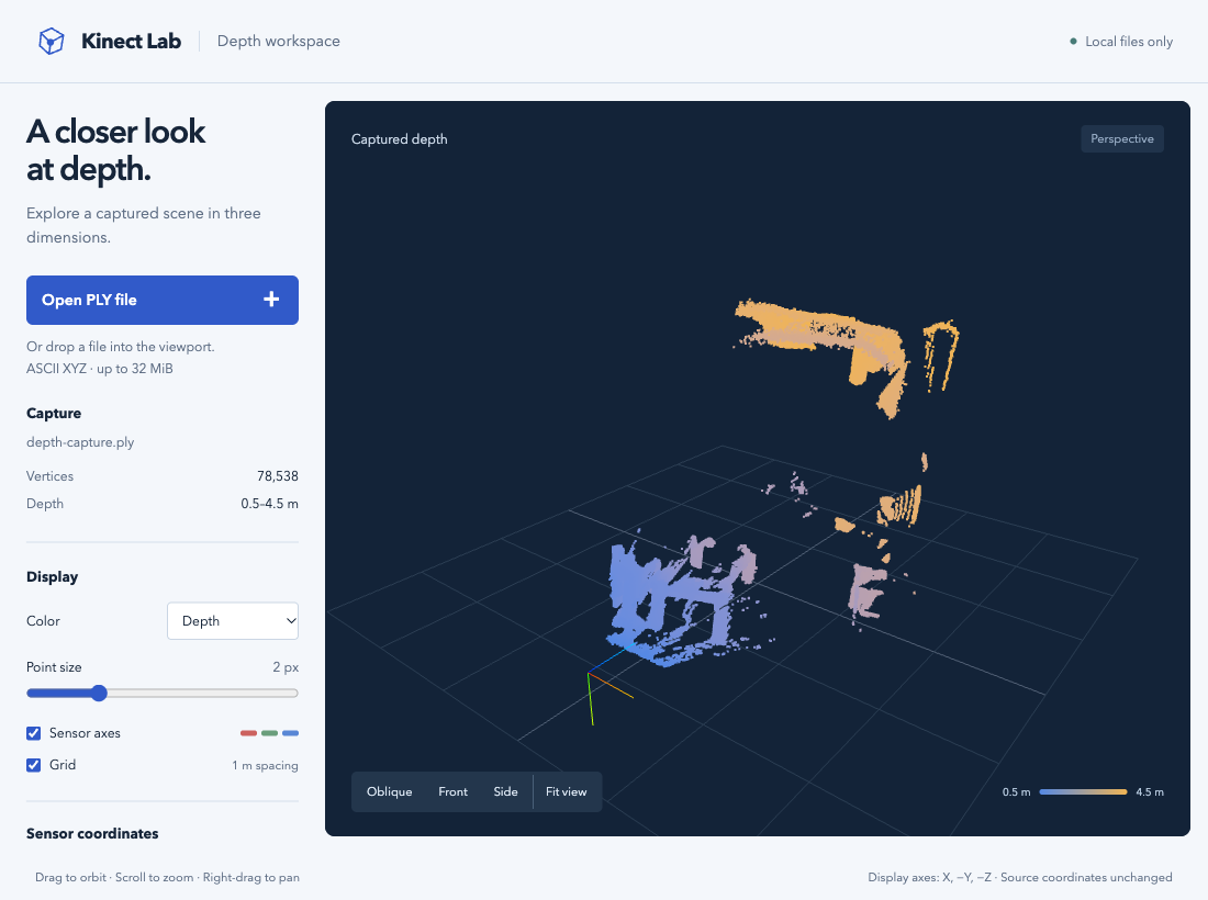
Here is that viewer with a real capture loaded:

The same exported frame throughout this article. Blue is nearer to the sensor, amber farther away. These are depth colors, not RGB from the Kinect. Open the full desktop capture.
Keeping the frame after the driver releases it
The first boundary is ownership. The driver delivers a depth frame in its own memory, and the listener expects that frame to be released. Letting a Rust slice outlive that release would make a very small bridge capable of a very unpleasant bug.
I chose to copy the pixels into Rust-owned storage. The CLI allocates a
reusable Vec<f32> with 512 × 424 initialized elements. The C++
bridge checks the destination size and the frame’s status,
shape and format before copying. A scope guard releases the native frames
before the call returns, including on an exception.
On the Rust side, the relevant method signature is below. This is an excerpt; its body is omitted.
pub fn next_depth<'a>(
    &mut self,
    timeout_ms: u32,
    pixels: &'a mut [f32],
) -> Result<Option<DepthFrame<'a>>, String>
The lifetime belongs to the caller’s pixel slice. While the returned
DepthFrame is in use, Rust prevents that storage from being overwritten
through another mutable borrow. A timeout returns None, so the previous
contents cannot accidentally be presented as a newly received frame.
The bridge passes an opaque capture handle, plain metadata and writable buffers across a C ABI. It does not expose C++ classes or containers to Rust. This keeps the unsafe Rust concentrated in one module, although the native implementation still has to honor the contract. Rust cannot check what an arbitrary C++ function does with a pointer.
This costs a copy of 868,352 bytes per frame. I have not measured the cost separately. For this version, having storage with an explicit owner is worth more to me than avoiding that copy.
I also keep the original representation: row-major float32 depth in millimetres. Zero, negative and nonfinite samples stay in the raw buffer; statistics exclude them. Replacing missing samples during acquisition would erase information I might need when investigating the saved frame.
Saving enough to project it again
A pixel’s depth does not provide its X and Y coordinates. I also need the camera calibration, including its focal lengths, principal point and lens distortion parameters.
The snapshot format stores the original float bit patterns
and frame metadata in frame.kdepth. A separate calibration.kcal
sidecar stores the nine factory IR parameters read from
the same open sensor. It includes the frame’s sequence number and timestamps;
loading checks those against the snapshot.
That association check catches a sidecar mixed up with another frame. Old depth-only snapshots remain readable, but point-cloud export refuses them rather than inventing calibration.

The files separate acquisition from inspection. Export uses the saved calibration; the browser only needs the resulting PLY.
The projection code follows the driver’s depth registration path. Rectification produces an image with lens distortion removed. For each output pixel in that image, the code uses the calibration to locate a source pixel in the raw frame, rounding to the nearest neighbour. Mappings outside the image are skipped.
Only after that lookup does it project the selected depth into 3D. This
excerpt comes after source sampling and the validity check in project:
let x = (column as f32 + 0.5 - cx) / fx * z;
let y = (row as f32 + 0.5 - cy) / fy * z;
Here z is already in metres. The 0.5 offsets follow the driver’s pixel-centre
convention. The exported coordinates use the depth camera’s frame: X
right, Y down, Z forward. There is no world alignment or RGB registration in
this export.
The exporter retains finite XYZ points with Z strictly above its float32 0.001 m cutoff. That is an export rule, separate from the finite-positive rule used for raw statistics. I am leaving the detailed distortion maths for another article; the essential point here is that the saved inputs are sufficient to repeat the calculation.
A file I can inspect without the sensor
The output is ASCII PLY: a header declaring the vertex count and properties, followed by one XYZ triplet per point. This is the complete header from the real export shown above:
ply
format ascii 1.0
comment units meters; camera axes X right Y down Z forward
element vertex 78538
property float x
property float y
property float z
end_header
There are no faces or colors. PLY gives me a recognizable format that can be inspected with ordinary text tools and read by software supporting XYZ point clouds. The units comment documents my coordinate convention.
The raw snapshot remains useful alongside it. The PLY has discarded pixel positions and invalid samples, so I cannot use it to reconstruct the original depth frame or try a different rectification strategy. For that, I return to the snapshot and its calibration.
For this capture, the final raw frame had 78,270 valid samples, while the export has 78,538 vertices. That difference follows from rectification: some valid raw samples are never selected, while others are selected more than once. The exported point count is not a count of independent measurements.
Repeating the export from the saved snapshot produced a byte-identical PLY. The actual capture files remain local and are not included in the public repository, so readers cannot download this same scene. The viewer includes a clearly labeled synthetic example for trying its controls without a Kinect capture.
Looking from somewhere else
Svelte handles file selection, errors and display controls. The browser reads
a selected file with File.text(); the application does not upload it.
Three.js receives the parsed coordinates as a Float32Array in a
BufferGeometry, rendered as Points.
The importer deliberately accepts a narrow PLY schema: ASCII 1.0, one vertex element and exactly float X, Y and Z. It rejects meshes, extra color properties and malformed data. Limits of 32 MiB and 217,088 vertices bound the accepted input. Coordinates are validated after float32 conversion. A depth that underflows to zero, or a coordinate that overflows to infinity, is rejected in the representation sent to the GPU.
The scene code leaves those source positions unchanged and rotates their containing group by half a turn around X. That displays (X, −Y, −Z), so the sensor’s up direction appears up on screen. The coordinate bounds in the sidebar still refer to the original sensor axes. I want to be able to compare a number in the PLY with a number on screen without undoing a display transformation in my head.
Orbit, zoom and pan are the useful part of the viewer. Front, side and oblique presets make it easy to return to a known viewpoint. Point size is in screen pixels, and I can switch to a single color when depth coloring gets in the way.
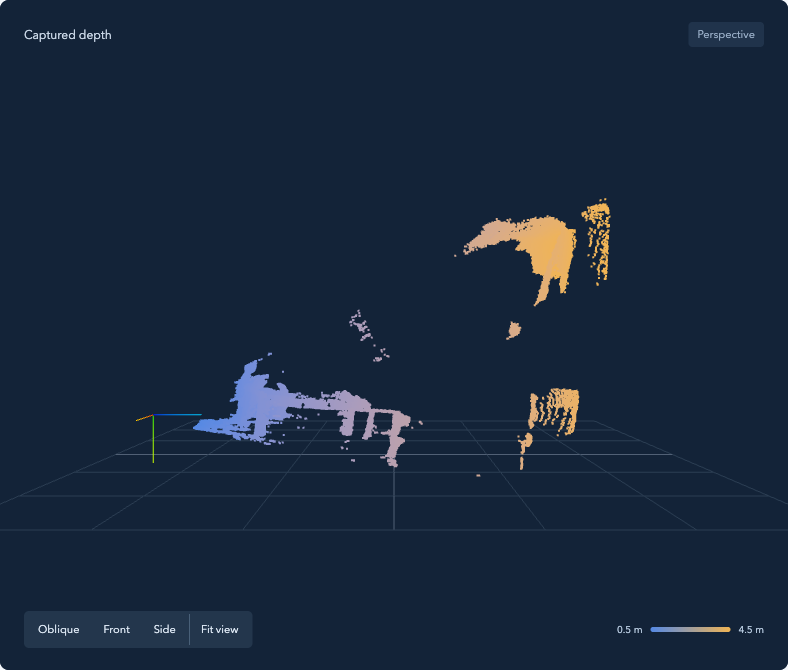
The side preset separates nearer and farther surfaces along the sensor’s depth axis. Areas hidden from the sensor remain empty from this viewpoint. Open this view at full size.
Depth coloring uses the loaded cloud’s original Z range, not distance from the current viewing camera. Rotating the view therefore keeps each point’s color stable. Here the range is approximately 0.5 to 4.5 m. Across different captures, the same color need not represent the same distance.
The sensor axes and metre grid help with orientation. The grid sits at the lowest displayed Y extent; it is a viewing aid, not a detected floor.
The framing helper accounts for portrait viewports. It also places the far clipping plane beyond the maximum zoom-out distance plus the cloud’s radius, measured from the framed target. A unit test checks that arithmetic. It does not cover a target panned far away from the cloud; camera limits relative to that moved target cannot guarantee that the original scene remains inside the clipping planes.
The viewer runs independently of Rust and the driver. After installing its dependencies, I can serve its built assets locally and open PLY files without an internet connection. It still needs a local HTTP server and a browser with WebGL 2. The repository’s README covers setup for the offline viewer at the linked revision.
Agreement with the driver has a precise meaning
I checked the geometry by feeding the saved raw frame and calibration to the
driver’s undistortDepth and getPointXYZ. After applying the same export
cutoff, both paths retained 78,538 points. Comparing the coordinates as
float32 values, no component differed by more than 2.4 × 10⁻⁷ m.
That small number measures agreement between calculations. It says nothing about the physical accuracy of the Kinect: both paths start from the same depth measurements and factory parameters, with no ground-truth distance.
Agreement on this frame also has a numerical boundary. During development, a synthetic calibration case placed a source coordinate near a half-pixel rounding boundary. Rust and C++ selected different neighbouring pixels, with substantially different depths in that fixture. The native regression test uses a calibration that avoids that ambiguity. The real capture comparison gives me useful evidence for this scene, not identical sampling for every possible calibration.
The capture that produced this frame saved its files, then hit the same USB shutdown error mentioned in the first article. The saved data let me continue checking the projection and viewer independently of that failure.
If a surface looks wrong, I can now compare the stored pixels, the projected coordinates and the browser view using the same input. Controlled measurements of physical accuracy still need their own experiment. For working on the geometry, I can return to this frame without another USB session.
Comments, questions, or just a reaction?
Send an email to ~bounga/bounga.org-discuss@lists.sr.ht. It is public and archived, so other readers can follow along and answer too.